| View previous topic :: View next topic |
| Author |
Message |
vespaclaire
Inspector

Joined: 20 Jul 2008
Posts: 231
Location: Aberdeenshire
|
 Posted: Sat Jan 03, 2009 5:46 am Post subject: Tips for fitting heated grips Posted: Sat Jan 03, 2009 5:46 am Post subject: Tips for fitting heated grips |
 |
|
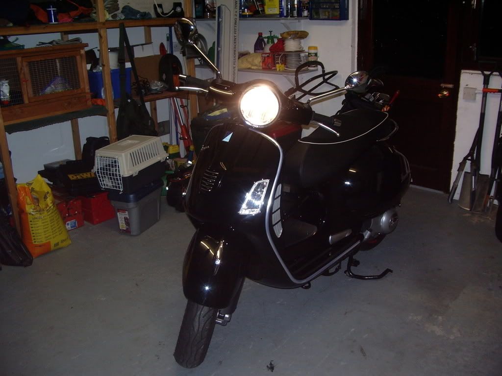
Work in progress
Tools required - screwdrivers, snips, inspection lamp, electrical crimpers, allen keys

Equipment required - Oxford 2008 heated grips, red male/female bullet crimps, electrical tape, relay, tie wraps, WD 40.


1. First do this! http://www.modernvespa.com/forum/topic7819 Yes I cheat
2. Do this http://www.modernvespa.com/forum/topic7431
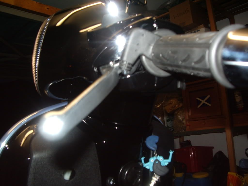
3. Remove the Bar ends
4. Work a thin screwdriver between the grip and bar, use still compressed air if you have access or use WD40 to unstick the glue. Work fast or the glue will re-stick. Tip do the left grip first as it easiest.
5. Do the same again with right grip, it is harder as it's the throttle and doesn't stop moving. I nearly gave up and cut it off with a knife, but I did manage.
6. On the throttle side the original plastic tube had a ridge at the end (on 300 anyway) I had to snip this edge away with a sharp pair of snips and then file down with fine file.
7. Have a cup of Tea
8. Remove the battery cover.
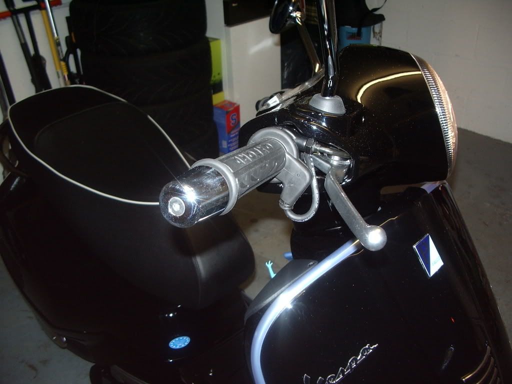
9. Fit the oxford hand grips to the scooter, do a dry fit. Don't glue until you are happy they are in correct place. Especially the throttle side.
10. Drill a 20mm hole inside the glove box (it's ok you dont see it)
The controler is inside the glove box, also I fitted the cable to my battery charger at the same time, so I don't need a screwdriver everytime I need to charge the battery 
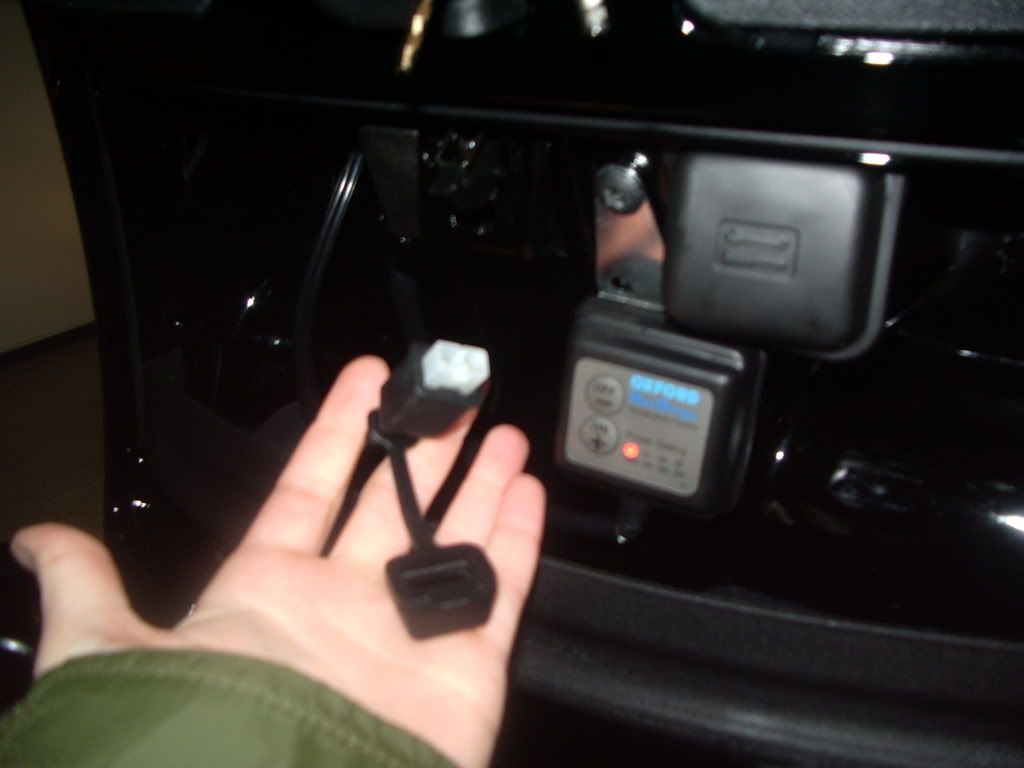
Not a great photo but I'm sure you get the picture. I was lucky that I could use the existing screw hole to fit the mounting bracket included in the kit, just had to stand on it to change the angle to get it to fit
Someone on here sugested not using the control unit and just using a simple goggle switch, I think this is a good idea cause 9 times out of ten the temp is up full butt. The 20mm hole I drilled Is just above where you see the cable disapearing. The reason I went for 20mm is so that I did not have to remove the plugs and sockets and I could feed them straight through, otherwise you would have to join the cables back up.
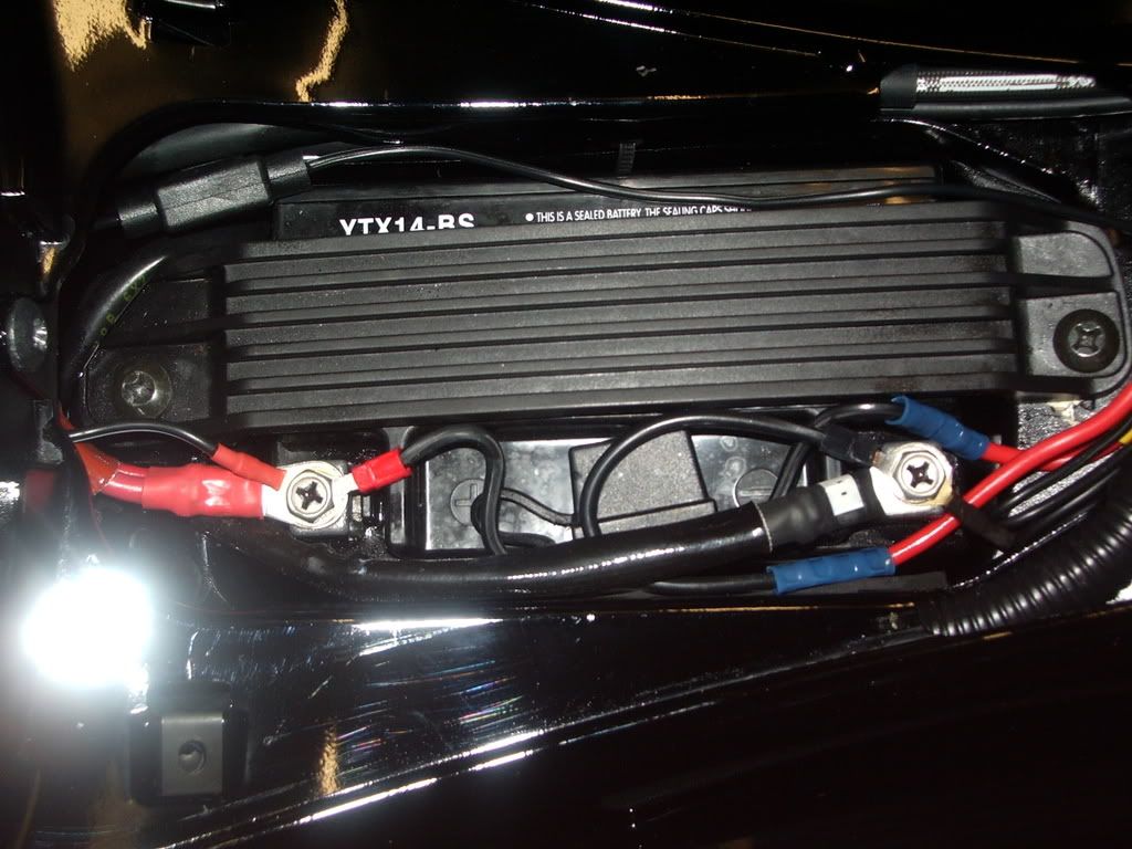
The battery spaggetti junction, why so many wires you ask? 1. Main feed 2. supply to battery charger 3. Supply to hotgrips Via 30amp relay
Had to chop and crimp connections as it is imposible to run the cables without removing the plug and sockets. I would recommend soldering connections as crimps not ideal with the vibration on a scooter.
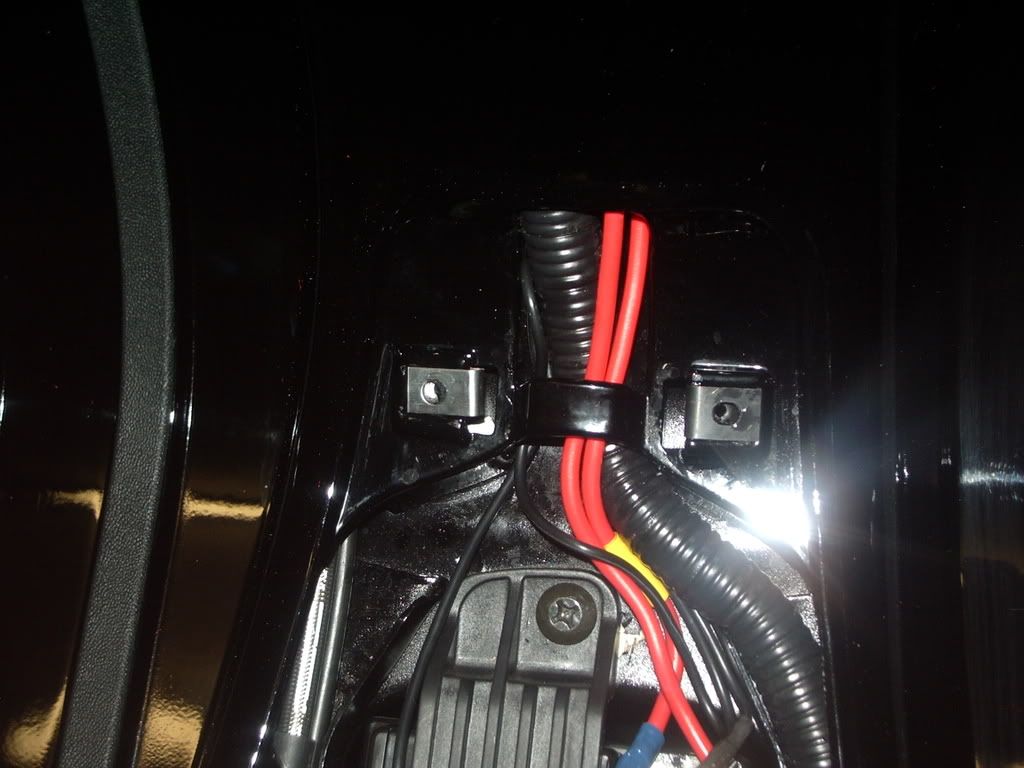
The cables feed up behind the glove box, tie wraped to the original loom, the 4 way 30amp relay is tie wraped behind the ignition.
Can't remember the exact cables I stole the power from, but it is from the ignition same as my tom tom and 12v plug. From behind left knee pad. You will need to confirm using a multimeter
A relay is a small plastic cube shaped thing with ( usually ) four terminals on it. The terminals are usually numbered 30, 87, 85 and 86. Get one that's suitable for the amount of current that you want to put through it, and wire it as follows : Pin 30 - permanent live ( can be taken direct from the battery positive terminal via a suitable fuse ). Pin 87 - this goes to the positive side of the component that you want to power up. Pin 85 - put this to a good earthing point. Pin 86 - wire this in to an ignition live feed in your wiring loom. Don't forget to earth the negative side of the component that you are wiring up. When you switch on your ignition, you put electricity through the relay via pin 86, this then goes through a coil of wire wrapped around an iron core, and earths via pin 85. This action causes an electro-magnet to pull down and bridge pins 30 and 87, thus powering up your component. You therefore only need heavy wiring on pins 30 and 87, and thin wiring on pins 85 and 86. you can also put an on/off switch in the wiring to pins 85 or 86, so that your component is not on all the time that the ignition is switched on. Hope that's all clear ! - here endeth the lesson.
Stolen from Jetex
My mates take the piss cause i'm the gadget queen. They keep asking when I'm getting sky fitted.
Hope this helps someone
_________________
GTS 300 is here and I LOVE IT!!!

http://www.bebo.com/Profile.jsp?MemberId=4301776581
Last edited by vespaclaire on Sat Jan 03, 2009 1:21 pm; edited 11 times in total |
|
| Back to top |
|
 |
Maver
Site Admin

Joined: 14 May 2007
Posts: 2193
Location: naaaaaarfolk we drive tractors and talk loike PIRATES
|
| Posted: Sun Jan 04, 2009 12:06 am Post subject: |
|
|
is this wiring diagram any good???
i think the "socket" refers to a 12v cig socket or could possibly be an "optimate" battery charger plug............. i'm no expert so i'm open to being corrected 
i notice also that rather than running a cable to the earth side of the battery connections to frame as earth is used.

_________________
 |
|
| Back to top |
|
|
CheekyThomas
Guvernor

Joined: 18 May 2007
Posts: 1374
|
| Posted: Sun Jan 04, 2009 10:19 am Post subject: |
|
|
Nice write up claire! 
Wiring diagram is good as well Mav... you can use a return earth on the machine, but direct to the battery (or main harness earth points) is a good idea especially on oxfords later digital heated grips as the controller is a little fuzzy...
... if you wanted a neater install, you could have wired the battery charger lead connections into the relay on pins 85+30 and had it all hidden behind the legshield. |
|
| Back to top |
|
|
Maver
Site Admin
Joined: 14 May 2007
Posts: 2193
Location: naaaaaarfolk we drive tractors and talk loike PIRATES
|
| Posted: Sun Jan 04, 2009 2:55 pm Post subject: |
|
|
| CheekyThomas wrote: | | Wiring diagram is good as well Mav... you can use a return earth on the machine, but direct to the battery (or main harness earth points) is a good idea especially on oxfords later digital heated grips as the controller is a little fuzzy... |
direct to battery it will be then
| CheekyThomas wrote: | | ... if you wanted a neater install, you could have wired the battery charger lead connections into the relay on pins 85+30 and had it all hidden behind the legshield. |
would the battery charger still work connected to the relay on those pins with the ignition off 
_________________
|
|
| Back to top |
|
|
Maver
Site Admin
Joined: 14 May 2007
Posts: 2193
Location: naaaaaarfolk we drive tractors and talk loike PIRATES
|
| Posted: Sun Jan 04, 2009 3:05 pm Post subject: |
|
|
would this be a suitable relay????
HALFORDS RELAY
_________________
|
|
| Back to top |
|
|
CheekyThomas
Guvernor
Joined: 18 May 2007
Posts: 1374
|
| Posted: Sun Jan 04, 2009 3:42 pm Post subject: |
|
|
Yes the battery would charge even with the ignition off... the relay is always connected to a live supply 
And yes that relay would do it... but ive got loads if you want one, ive got loads as i wire HID kits in with them |
|
| Back to top |
|
|
CheekyThomas
Guvernor
Joined: 18 May 2007
Posts: 1374
|
| Posted: Sun Jan 04, 2009 3:49 pm Post subject: |
|
|
Also got a few sets of Motopart heated grips too... only 2 setting heat control though... think they retail at about £24.99 but would be less to club members, i can find out if ya want...
 |
|
| Back to top |
|
|
Maver
Site Admin
Joined: 14 May 2007
Posts: 2193
Location: naaaaaarfolk we drive tractors and talk loike PIRATES
|
| Posted: Sun Jan 04, 2009 4:42 pm Post subject: |
|
|
| CheekyThomas wrote: | | ... if you wanted a neater install, you could have wired the battery charger lead connections into the relay on pins 85+30 and had it all hidden behind the legshield. |
| CheekyThomas wrote: | | Yes the battery would charge even with the ignition off... the relay is always connected to a live supply |
ok, seems the way to go
next question.....
do you just crimp 2 wires into the spade connectors for pins 85 + 30 to do this? is there room in the spade connector for 2 wires?
_________________
|
|
| Back to top |
|
|
Doug
Sargeant
Joined: 22 Aug 2008
Posts: 57
Location: Southport
|
| Posted: Sun Jan 04, 2009 5:27 pm Post subject: |
|
|
My heated grips were delivered yesterday - so will be following your guide sometime this week.
Many thanks
_________________
 |
|
| Back to top |
|
|
CheekyThomas
Guvernor
Joined: 18 May 2007
Posts: 1374
|
| Posted: Sun Jan 04, 2009 5:30 pm Post subject: |
|
|
| If theres not enough room in the connector for both wires, then just splice slightly further up, but normally there is as the battery charger wires are very thin... is it an optimate charger youve got?? |
|
| Back to top |
|
|
Maver
Site Admin
Joined: 14 May 2007
Posts: 2193
Location: naaaaaarfolk we drive tractors and talk loike PIRATES
|
| Posted: Sun Jan 04, 2009 5:41 pm Post subject: |
|
|
yep, optimate
_________________
|
|
| Back to top |
|
|
Maver
Site Admin
Joined: 14 May 2007
Posts: 2193
Location: naaaaaarfolk we drive tractors and talk loike PIRATES
|
| Posted: Sun Jan 04, 2009 5:48 pm Post subject: |
|
|
so what colour (therefore size) crimp on terminals should i be looking at using for the relay? same size ring terminals for battery?
_________________
Last edited by Maver on Sun Jan 04, 2009 5:49 pm; edited 1 time in total |
|
| Back to top |
|
|
CheekyThomas
Guvernor
Joined: 18 May 2007
Posts: 1374
|
| Posted: Sun Jan 04, 2009 5:48 pm Post subject: |
|
|
| Yeah thats ok then... nice small leads... if ya need more connectors for optimates i guess ya know they are tamiya radio controlled car battery connectors... about £3 for 10 just reverse the colours |
|
| Back to top |
|
|
Maver
Site Admin
Joined: 14 May 2007
Posts: 2193
Location: naaaaaarfolk we drive tractors and talk loike PIRATES
|
| Posted: Sun Jan 04, 2009 5:50 pm Post subject: |
|
|
| CheekyThomas wrote: | | Yeah thats ok then... nice small leads... if ya need more connectors for optimates i guess ya know they are tamiya radio controlled car battery connectors... about £3 for 10 just reverse the colours |
didn't know that.......
where do we buy these things of wonder
are these the right things?? ebay item number 200294115700
_________________
|
|
| Back to top |
|
|
CheekyThomas
Guvernor
Joined: 18 May 2007
Posts: 1374
|
| Posted: Sun Jan 04, 2009 6:16 pm Post subject: |
|
|
| Yeah they are the ones... i got my work supply from a little local RC shop... they come built with about 10cm of wire sticking out and i just solder joints on.. but he only has one half (to end you need for wiring onto the bike, not the charger end)... they were about 70p each. |
|
| Back to top |
|
|
|


